

 By ATN Editorial Team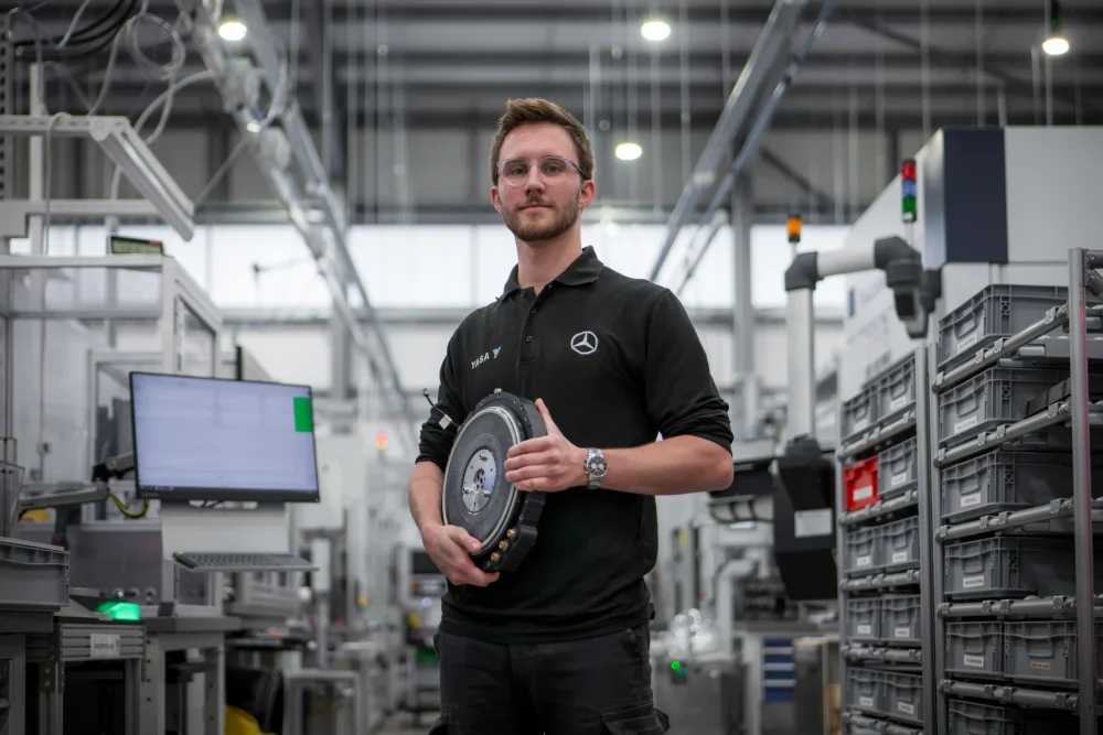
Modern electric vehicle propulsion is shaped by three primary ceilings — the electromagnetic torque the motor can produce, the thermal envelope its cooling system can sustain, and the mechanical limits on rotor speed. Inverter current and DC bus voltage, insulation systems, bearing DN limits, demagnetisation margin and NVH all become first-order constraints in specific designs. Mass is largely a consequence of balancing those constraints, although in automotive applications it is also an explicit optimisation target in its own right because of vehicle dynamics, unsprung mass, crash integration, packaging and BOM cost. A high power density motor is one that compounds those constraints favourably enough to deliver more useful continuous power per kilogram and per litre than a comparable peer.
The first complication for an engineer reading kW/kg figures is that the denominator varies wildly across the industry. Motor-only mass, motor plus inverter, full e-axle including a single-speed gearbox, active mass excluding housing, or dry mass excluding coolant are all used interchangeably in marketing material. Direct comparison between figures from different vendors is rarely apples-to-apples, and OEMs frequently publish nothing at the motor-only level at all. With that caveat in mind, system-level (motor + gearbox + inverter) figures for mainstream production BEV e-axles sit in the low single digits per kilogram, with the motor itself typically a few kW/kg higher under a motor-only boundary. Peak figures are generally higher than continuous, depending on rating regime. Demonstrator and motorsport machines have pushed peak motor-only figures past 30 kW/kg, with YASA’s most recent prototype claiming 59 kW/kg peak under a short-duration motor-only boundary the company defines. This explainer covers the motor topologies in play, what physically limits power density, why cooling architecture is usually the dominant constraint on continuous rating, the materials and winding choices behind today’s best numbers, and the trade-offs that explain why production hardware lags demonstrator records.
How Engineers Define A High Power Density Motor
The single most-quoted figure, kW/kg (gravimetric or specific power density), is also the most overloaded. The “kg” can mean the motor housing alone, the motor and rotor only, or the full eDrive — motor plus inverter plus reducer plus cooling. The same physical machine can be marketed as 8 kW/kg or 5 kW/kg depending on which definition is chosen. Volumetric power density, kW/L, is the metric the US Department of Energy’s EV powertrain roadmap has used as a directional target — around 50 kW/L — and is a better fit for packaging engineers.
The peak-versus-continuous distinction is usually more important than the gravimetric-versus-volumetric one. Peak power density is what the motor delivers for a 10–30 second burst, limited by the thermal mass of the windings and the PWM current ceiling. Continuous power density is what the cooling system can sustain indefinitely. Peak figures in production hardware are typically around 1.5 to 3 times higher than continuous, with demonstrators and motorsport machines exceeding that ratio. Engineers reading a vendor datasheet should treat the headline number as bounded by the rating regime, which is rarely identical across vendors.
Motor Topologies And Their Power-Density Trade-Offs
Five topologies matter for road-vehicle propulsion. Interior permanent magnet synchronous machines (IPM PMSM) are the dominant production choice — Tesla Model 3 rear, the Volkswagen MEB APP550, the Hyundai E-GMP rear unit, Toyota and Lexus hybrid drives and the GM Ultium platform all use IPM rotors. IPM machines combine magnetic torque with a reluctance-torque contribution that typically sits in the order of 10–30% of total torque, depending on the saliency ratio (Lq/Ld), which is usually 2–3 in EV traction designs. The field-weakening behaviour gives a constant-power speed range of 2–3:1. The drawback is rare-earth magnet content (neodymium plus dysprosium or terbium for thermal stability) and the cost floor that puts under the bill of materials.
Induction motors (ACIM) trade some peak torque density for rare-earth-free operation, although modern copper-rotor designs have closed much of the gap that older aluminium-rotor induction machines suffered. Tesla still uses copper-rotor induction motors on the front axle of dual-motor S, X and Y variants. They avoid the permanent-magnet drag losses seen in PM machines when de-energised — useful for efficient highway cruise — at the cost of higher rotor losses under load.
Externally-excited synchronous motors (EESM or WRSM) replace the rotor’s permanent magnets with a wound rotor coil and slip rings or a brushless exciter. Renault uses an EESM derivative on the Mégane and Scénic E-Tech; BMW’s fifth-generation eDrive used in the i4, i5, i7 and iX is EESM, and BMW has publicly cited a power-to-weight improvement over its previous generation, although exact metrics depend on the comparison baseline. EESM avoids rare-earth magnets entirely and lets the controller modulate the field for part-load efficiency, at the cost of rotor copper losses and somewhat lower peak power density.
Axial flux permanent magnet (AFPM) machines flow flux parallel to the rotor axis through pancake-shaped rotor/stator pairs. The geometry packs a larger mean active radius into a compact axial envelope and shortens the magnetic path, which gives the topology a structural torque-density advantage over radial machines for a given motor envelope. The relationship is sometimes summarised as “cubic” scaling, although real behaviour depends on diameter, axial length, air-gap flux density and thermal constraints rather than a strict cube law. YASA reports substantially lower iron usage than comparable radial-flux machines, with reductions approaching 80% in its own comparisons — figures that are baseline-dependent and not independently benchmarked. AFPM is in production for performance hybrids — McLaren Artura’s 15.4 kg axial-flux e-motor, Ferrari SF90 — and Mercedes-AMG is preparing its AMG.EA platform with YASA-derived three-motor architecture for production at Marienfelde from 2026. YASA’s 2025 record motor illustrates how far the topology can be pushed.
Switched reluctance motors avoid magnets and rotor windings entirely. They are rugged, fault-tolerant and cheap, but the torque ripple and acoustic noise inherent to a doubly-salient geometry have kept them out of passenger cars to date. Modern current-shaping control has narrowed the NVH gap, and switched reluctance is being revisited for cost-sensitive segments where rare-earth supply pressure is acute.
The Three Bottlenecks On A High Power Density Motor
Torque scales with magnetic loading B, electric loading A and machine volume; power equals torque multiplied by speed. Push any of those three and power density rises.
Magnetic loading is capped by the saturation flux density of the stator iron (1.6–2.2 T for conventional silicon steel) and the remanence of the rotor magnets (NdFeB at 1.2–1.4 T, samarium cobalt at 1.0–1.1 T, ferrite at 0.4 T). Cobalt-iron alloys (Vacoflux 49, Vacodur) push saturation to around 2.3 T and are widely reported as used in Formula 1 MGU-K rotors and aerospace motors, although F1 teams rarely disclose material choices. Material price is significantly higher than for silicon steel.
Electric loading — amperes per metre of stator circumference — is limited by thermal performance, because copper losses scale with the square of current. Modern hairpin stators with direct oil cooling support reported continuous conductor current densities in the order of 20–30 A_rms/mm², although the exact figure varies with the definition used (slot-average vs conductor-only, RMS vs peak). Direct conductor cooling, where coolant flows inside hollow conductors, has been demonstrated at up to roughly 75 A/mm² in research and motorsport contexts — well above what is currently achievable in series-production hardware.
Rotor speed is the third lever and often the most direct route to higher kW/kg, even if it is rarely easy in practice. Power is torque multiplied by speed, so raising rpm and gearing down the reduction ratio raises kW/kg without raising torque density at all. Lucid Air’s drive unit runs at 20,000 rpm, Equipmake’s Ampere at 30,000 rpm, and Tesla’s Plaid rear motor uses a carbon-fibre sleeve over the rotor to contain hoop stress at very high rpm. The trade-offs are rotor mechanical stress, bearing duty, gear losses, NVH and frequency-dependent iron and AC copper losses.
Cooling Is The Real Limit On Continuous Power Density
For most production motors in 2026, cooling architecture is often the dominant practical constraint on continuous kW/kg, although saliency ratio, magnet selection, flux concentration, air-gap design and iron-loss management still fundamentally shape the ceiling cooling has to work against. The progression runs: water-glycol jacket around the stator (cheap, simple, limited); direct oil spray onto end-windings (Tesla Plaid, Lucid Air, Porsche Taycan); slot oil cooling with channels integrated into the stator slot (pushed by YASA, BorgWarner and Magna); and direct conductor cooling, where coolant flows inside hollow copper conductors. Direct conductor cooling has been the domain of Formula 1 KERS hardware and the Koenigsegg Quark research motor. Recent announcements, including Hyperdrives’ work on a more manufacturable hollow-conductor process, suggest the topology could begin migrating toward higher-volume production over the next product cycle.
The reason cooling is the dominant practical lever on continuous rating is straightforward: moving heat extraction closer to the conductor lets the designer support significantly higher current density before the windings overheat, although the relationship is not strictly linear because copper loss scales with the square of current and iron and saturation losses scale differently. Reported winding temperature rises drop substantially when heat extraction moves to the conductor — from tens of degrees with jacket cooling to single-digit to low-tens-of-degrees with direct conductor cooling under specific test conditions. That headroom is part of what separates a high-peak demonstrator from a high-continuous production unit. Adjacent work on AI-assisted thermal management — ZF’s TempAI — targets the same envelope from the control side.
Hairpin Windings And Conductor Choice
Hairpin windings — rectangular cross-section copper bars formed into hairpin shapes, inserted through the stator slots and welded at the end-turn — have replaced random round-wire windings in most modern BEV traction motors. Slot fill factor rises from around 50% for round wire to 70–75% for hairpins, end-turns shorten, and slot-to-iron thermal contact improves. The Volkswagen APP550, GM Ultium, Hyundai E-GMP, BMW Gen5 and Stellantis STLA motors all use hairpin stators. Continuous-wound bar winding offers a theoretical further uplift in fill factor, but remains significantly harder to manufacture at scale. Round-wire windings are still used in some high-frequency machines, in axial-flux architectures with concentrated windings, and in premium designs where AC copper loss matters more than slot fill.
Litz wire — many fine insulated strands twisted together to break up eddy currents — becomes increasingly attractive as electrical frequency rises into the high hundreds of Hz and above. Skin and proximity effects in solid hairpin conductors raise AC copper losses with increasing frequency, although whether Litz pays off depends on strand diameter, conductor geometry, slot geometry, PWM harmonics and switching frequency rather than a single threshold.
Magnets, Steel And The Rare-Earth Question
Sintered neodymium-iron-boron magnets with grain-boundary diffusion of dysprosium or terbium remain the workhorse of automotive PMSM rotors. The heavy rare-earth additions raise the magnet’s coercivity (resistance to demagnetisation at high temperature) without using much heavy material — a step-change in cost-efficiency that landed in series production over the last decade. Geopolitical pressure on rare-earth supply, principally from China’s export controls, has pushed the industry toward HRE-reduction strategies at varying levels of maturity. The Honda–Daido HRE-free NdFeB has been in production use in the Honda Freed hybrid since 2016. Toyota has announced a 50% neodymium-reduced magnet using lanthanum and cerium, although broad in-vehicle deployment is still being clarified. Stellantis and Niron Magnetics are working on iron-nitride (Fe16N2) magnets at pre-production stage. The direction of travel is consistent even if production penetration is still limited. Rare-earth-free architectures generally shift cost and mass elsewhere — EESM trades magnet cost for rotor copper losses, ferrite-only designs trade flux density for cost — so the substitution is not efficiency-neutral.
Electrical steel choices have a quieter but real impact. Thinner laminations — around 0.20 mm in modern BEV traction stators, and as fine as 0.10 mm in some motorsport and aerospace applications — reduce iron loss at high fundamental frequency. Cobalt-iron alloys add roughly 0.3 T of saturation headroom over silicon steel — a 20% increase in achievable torque density — at the cost of significantly higher material price.
Inverter Co-Design — SiC And 800 V Architectures
A high power density motor is increasingly a system-level claim, not a motor-only one. Silicon carbide inverters (Tesla Plaid, Lucid, Hyundai E-GMP, Porsche Taycan) replace silicon IGBTs with SiC MOSFETs, cutting switching losses and allowing higher PWM frequency. The motor designer can then run a higher fundamental frequency, reduce iron mass and recover some of the savings as power density. Eight-hundred-volt traction architectures (Porsche Taycan, Hyundai E-GMP, Lucid, Kia EV9, BMW Neue Klasse) roughly halve the current at a given power, which in turn reduces inverter and cable mass. System-level mass reduction is not strictly linear, and once inverter and cable savings have been captured the marginal benefit plateaus; cost increases from higher-voltage components can also offset the packaging gains. Integrated “3-in-1” drive units that share housing and coolant between motor, inverter and reducer give a system kW/kg uplift even when the motor itself is unchanged. The integration trend continues into 8-in-1 units that also fold in the DC-DC converter and onboard charger.
State-Of-The-Art Numbers In 2026
A few benchmarks anchor the kW/kg conversation, with the usual caveats on what is in the kilogram. YASA’s latest demonstrator delivers 750 kW peak from 12.7 kg, which the company quotes as approaching 60 kW/kg peak and roughly 27 kW/kg continuous under a motor-only boundary it defines — the highest published number in the segment and the basis for the AMG.EA platform. McLaren’s Artura uses a 15.4 kg axial-flux unit producing 70 kW peak (4.6 kW/kg) in its torque-fill role alongside the V6. Lucid Air’s drive unit (motor, inverter, transmission and differential) delivers approximately 485 kW peak from 74 kg — about 6.5 kW/kg peak at the drive-unit level — with the motor turning to 20,000 rpm. Lucid’s published volumetric figure is 41 hp/L (roughly 30.6 kW/L) at the drive-unit level. Motor-only continuous kW/kg figures are not publicly disclosed. Koenigsegg’s Quark research motor claims 8.3 kW/kg peak (250 kW from under 30 kg) with direct conductor cooling. Formula E’s upcoming Gen4 platform builds on the Gen3 Evo era, whose complete powertrain package (motor, single-speed reduction, differential and inverter) weighs 32 kg and delivers up to 350 kW peak in attack mode — around 11 kW/kg peak at the package level rather than motor-only. BMW’s fifth-generation EESM is quoted at a 30% improvement on the previous generation. Donut Lab’s in-wheel motor claims 15.75 kW/kg (630 kW from 40 kg) at the wheel hub.
These numbers should be read with three caveats in mind: vendor-quoted figures are usually peak, the denominator varies between motor-only and drive-unit, and the rotor sleeve or housing may or may not be included. Until independently measured benchmarks appear, the contested superlatives should be framed as “the company claims”.
Where High Power Density Motors Are Going
Four directions are converging. Axial flux is moving from low-volume premium hybrids (McLaren Artura, Ferrari SF90 HEV) toward larger-scale production, with Mercedes-AMG.EA the first large-scale premium EV test case; if the 2026 production ramp at Marienfelde holds, industry press reports suggest BMW’s M division and Allison are also evaluating similar topologies, although neither has confirmed publicly. Rare-earth-reduction strategies — Toyota’s lanthanum/cerium magnet, the Niron Magnetics Fe16N2 partnership with Stellantis, the Honda–Daido HRE-free NdFeB — are moving from R&D into the supply chain in response to Chinese export controls. Voltage continues to climb — 800 V is becoming established in premium EV platforms, with 900–1000 V appearing in heavy-duty applications and the BMW Neue Klasse. Direct conductor cooling is moving out of motorsport and into manufacturable processes. And in-wheel motors, dismissed for a decade on unsprung-mass grounds, are getting another look from established players and start-ups, although the sceptics on brake integration and warranty cost have not yet been fully answered.
Bottom Line For Engineers Specifying A Traction Motor
For an automotive engineer choosing a motor architecture in 2026, the trade space looks like this. If maximum power density is the goal and unit cost is secondary, axial flux PM is the topology to investigate, with the caveat that volume production at passenger-car scale is still being proven. If rare-earth content is a constraint — for cost, supply or end-of-life reasons — EESM (Renault, BMW) or copper-rotor induction (Tesla front motors) is the obvious path. If the application is a mainstream passenger BEV with packaging room for a hairpin-stator radial machine and the inverter can be SiC, an IPM PMSM at 5–8 kW/kg continuous is the default and likely to remain so. What separates a high power density motor from an average one in 2026 is rarely the electromagnetic design alone. Cooling architecture, inverter co-design and system integration are increasingly dominant constraints, although electromagnetic design choices still matter significantly.
For more high power density motor news, click here.
Frequently Asked Questions
A high power density motor is an electric motor that delivers more useful continuous power per kilogram and per litre than a comparable peer. Mainstream production e-axles in 2026 sit in the low single digits per kilogram at the system level (motor + gearbox + inverter), with the motor itself a few kW/kg higher under a motor-only boundary; OEMs rarely publish like-for-like motor-only kW/kg, which limits direct comparison. Demonstrator and motorsport machines push peak figures above 30 kW/kg, with YASA’s latest axial flux prototype claiming peak figures approaching 60 kW/kg under specific motor-only boundary definitions.
Peak power density is what the motor delivers in a 10-30 second burst, limited by the thermal mass of the windings and the PWM current ceiling. Continuous power density is what the cooling system can sustain indefinitely. Peak is typically around 1.5-3 times higher than continuous in production hardware, with demonstrators and motorsport machines exceeding that ratio. Vendor headline numbers should be read with the rating regime in mind, since boundaries are rarely consistent across vendors.
In a radial machine torque scales with the square of diameter and the length of the active stack. In an axial flux machine the rotor and stator are pancake-shaped and torque benefits more strongly from rotor diameter, because the geometry packs more active radius into the same envelope. The result is more torque per unit envelope at the same diameter; the relationship is often summarised as cubic but the real behaviour is design-dependent. The trade-offs are tighter air-gap tolerance, cooling complexity and current production volume.
Most high power density production motors still use neodymium-iron-boron magnets with dysprosium or terbium additions for thermal stability. Externally-excited synchronous (Renault, BMW Gen5) and copper-rotor induction (Tesla front motor) avoid rare earths entirely. R&D programmes including Toyota’s lanthanum/cerium magnet, the Niron Magnetics iron-nitride collaboration with Stellantis, and Honda/Daido’s HRE-free NdFeB are moving toward production but have not yet displaced standard NdFeB in mass-market traction motors.
In 2026, cooling architecture is often the dominant practical lever on continuous rating, although saliency ratio, magnet selection and iron-loss design still fundamentally shape the ceiling. A water-glycol jacket sets a low continuous rating. Direct oil spray onto end-windings (Tesla Plaid, Lucid Air, Porsche Taycan) raises it. Slot oil cooling raises it further. Direct conductor cooling, where coolant flows inside hollow copper conductors, materially reduces winding temperature rise under high load — from tens of degrees with jacket cooling to single-digit to low-tens-of-degrees under specific test conditions — which is part of the headroom that separates a peak rating from a continuous one.
